MicroBio MB2 Bioaerosol Sampler - Operating Manual
For products manufactured before October 2023 please contact Cantium Scientific Ltd or refer to the instructions supplied with the device.
- 1. Regulatory Compliance
- 2. WEEE and Recycling
- 3. Warranty
- 4. MicroBio MB2 Technical Specification
- 5. MicroBio MB2-HiFlow Technical Specification
- 6. MicroBio MB2-RSH Technical Specification
- 7. Introduction
- 8. Battery and External Power
- 9. Battery Management
- 10. IQ / OQ / PQ
- 11. Sampling
- 12. Selection of Media
- 13. Inserting a Contact Plate or Petri Dish
- 14. Dust Cover (optional)
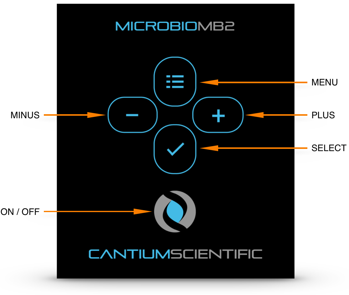
- 15. Keypad Controls
- 16. Switching On and Off
- 17. Take a Sample
- 18. Delayed Sample
- 19. Sequential Sampling
- 20. User Presets
- 21. Unit Status
- 22. Settings
- 23. Tripod Mounting
- 24. Temperature and Humidity
- 25. Determining Results
- 26. Change Plate / Dish Type
- 27. Head Seal Maintenance
- 28. Cleaning
- 29. Validation
- 30. Calibration
- 31. Troubleshooting and Technical Support
- 32. Appendix A - 220 Hole Count Correction Table
- 33. Appendix B - 400 Hole Count Correction Table
- 34. Appendix C - Culture Media Types
- 35. Appendix D - Replacement Parts
- 36. Appendix E - MB2-RSH Installation
1. Regulatory Compliance
EC Declaration of Conformity
This is to certify that MicroBio MB2 products manufactured from April 2017 comply with the essential requirements of the following European Community Directives when used according to their intended purpose:
Electromagnetic Compatibility (EMC) Directive 2014/30/EU
BS EN 61326-1:2013 - Scientific, Test and Measurement Equipment
Referencing:
BS EN 55011/CISPR11 - Emissions for Industrial, Scientific and Medical Equipment
BS EN 61000-4-2 - Immunity to Electrostatic Discharge
BS EN 61000-4-3 - Radiated Immunity
Restriction of the Use of Certain Hazardous Substances (RoHS-3) in Electrical and Electronic Equipment (EEE) Directive (EU 2015/863).
2. WEEE and Recycling
At the end of this product's life, please dispose at an appropriate recycling centre, or return it to your local distributor who, depending on local laws, may be obliged to take the product for safe recycling and disposal.
The MicroBio MB2 key parts are manufactured from the following:
Part |
Material |
Recyclable |
Blower housing |
Aluminium |
Yes |
Air blower * |
Body and rotary vanes: Glass reinforced nylon
Motor: Steel, copper, rare earth magnets, and others |
Yes (limited facilities) |
Enclosure |
ABS Plastic |
Yes |
Display window |
Polycarbonate |
Yes |
Tripod mount |
Aluminium |
Yes |
Screws and washers |
Stainless steel |
Yes |
Circuit board, wires * |
Various |
Partially |
Sampling heads |
Stainless steel or aluminium |
Yes |
Carry case |
ABS Plastic |
Yes |
Packaging |
Cardboard and PET |
Yes |
Documentation |
Paper |
Yes |
Batteries * |
NiMH |
Partially |
* These items must be taken to approved recycling centres equipped to handle such waste and recover the metals used in their manufacture. Some elements of these parts cannot be recycled.
3. Warranty
The manufacturer warrants this product to be free from defects in materials and workmanship for 36 months from the date of purchase.
If your product is found to be defective within that period, please contact Cantium Scientific Limited or your local distributor who will arrange for repair of the instrument, or if necessary a replacement.
This warranty does not cover accidental damage, wear and tear, incorrect use, consequential or incidental loss. The warranty excludes rechargeable cells supplied with the sampler.
Damage caused by cleaning materials and methods not recommended by the manufacturer, use beyond the specification, use in wash down areas (unless used in approved protective bags), or modifications without prior permission from the manufacturer will invalidate the warranty.
This warranty does not affect your statutory rights.
4. MicroBio MB2 Technical Specification
Flow Rate: |
100 L.min-1 ‡ |
Sample Volume: |
10 to 10000 litres in varying steps |
Sampling Volume Capacity: |
~ 60000 litres before recharge* |
d50 Particle size: |
1.7 µm (220 x 1mm hole head) 1.35 µm (400 x 0.7mm hole head) |
Mean particle velocity: |
9.62 ms-1 (220 x 1mm hole head) 10.7 ms-1 (400 x 0.7mm hole head) |
Weight (excluding charger and carry bag): |
780 g (inc. battery and petri dish) |
Dimensions: |
196 x 100 x 110mm (inc. head) sold to August 2025 196 x 100 x 116 (inc. head) sold from September 2025 |
Power: |
4 x AA NiMh Cells |
Noise Level: |
< 75dB @ 1m |
Environmental Operating Range: |
-10 to 50°C up to 90% RH‡ |
Sampling Plate: |
55mm/65mm contact plate or 90mm petri dish |
Sampling Head: |
316 grade stainless steel 220 x 1mm holes or Anodised aluminium 400 x 0.7mm holes or 316 grade stainless steel 400 x 0.7mm holes |
* Based upon random samples until low battery warning given. These tests were undertaken on units fitted with new and fully charged Ansmann Max-e 2500 mA.Hr NiMh cells. Actual battery life may vary due to volume taken per sample, interval between samples, age of cells, and other environmental effects, such as humidity and temperature.
‡ Calibrated at 1013mbar 20ºC. Environmental conditions will affect air pressure thus mass/volumetric flow rates.
5. MicroBio MB2-HiFlow Technical Specification
Flow Rate: |
180 L.min-1 ‡ |
Sample Volume: |
10 to 10000 litres in varying steps |
Sampling Volume Capacity: |
~ 40000 litres before recharge* |
d50 Particle size: |
1.71 µm |
Mean particle velocity: |
9.55 ms-1 |
Weight (excluding charger and carry bag): |
840g (inc. battery and petri dish) |
Dimensions: |
196 x 100 x 110mm (inc. head) |
Power: |
4 x AA NiMh Cells |
Noise Level: |
< 80dB @ 1m |
Environmental Operating Range: |
-10 to 50°C up to 90% RH‡ |
Sampling Plate: |
90mm petri dish |
Sampling Head: |
Stainless Steel 400 x 1.0mm holes |
* Based upon random samples until low battery warning given. These tests were undertaken on units fitted with new and fully charged Ansmann Max-e 2500 mA.Hr NiMh cells. Actual battery life may vary due to volume taken per sample, interval between samples, age of cells, and other environmental effects, such as humidity and temperature.
‡ Calibrated at 1013mbar 20ºC. Environmental conditions will affect air pressure thus mass/volumetric flow rates.
6. MicroBio MB2-RSH Technical Specification
Flow Rate: |
100 L.min-1 ‡ |
Sample Volume: |
10 to 10000 litres in varying steps |
Sampling Volume Capacity: |
~ 60000 litres before recharge* |
d50 Particle size: |
1.7 µm (220 x 1mm hole head) 1.35 µm (400 x 0.7mm hole head) |
Mean particle velocity: |
9.62 ms-1 (220 x 1mm hole head) 10.7 ms-1 (400 x 0.7mm hole head) |
Weight (excluding charger and carry bag): |
1680 g (inc. controller, head unit, battery, cable, petri dish) |
Dimensions: |
196 x 100 x 40mm (control unit) 140 x 100 x 100mm (head unit) |
Power: |
4 x AA NiMh Cells |
Noise Level: |
< 75dB @ 1m (sampling unit) |
Environmental Operating Range: |
-10 to 50°C up to 90% RH‡ |
Sampling Plate: |
55mm/65mm contact plate or 90mm petri dish |
Sampling Head: |
316 grade stainless steel 220 x 1mm holes or Anodised aluminium 400 x 0.7mm holes or 316 grade stainless steel 400 x 0.7mm holes |
* Based upon random samples until low battery warning given. These tests were undertaken on units fitted with new and fully charged Ansmann Max-e 2500 mA.Hr NiMh cells. Actual battery life may vary due to volume taken per sample, interval between samples, age of cells, and other environmental effects, such as humidity and temperature.
‡ Calibrated at 1013mbar 20ºC. Environmental conditions will affect air pressure thus mass/volumetric flow rates.
7. Introduction
The MicroBio MB2 is part of the MicroBio range of bioaerosol samplers and is one of the most economical hand-held samplers in the world for monitoring airborne micro-organisms or bioaerosols. It is available with a standard flow rate of 100 litres per minute or the HiFlow model with a flow rate of 180 litres per minute.
The MicroBio range meets the standard required for a reference sampler, as fully validated by the UK Department of Trade and Industry Validation of Analytical Methods (VAM) programme. They are designed and tested to meet the requirements of ISO14698, EN 17141-2020 and USP797 requirements.
The sampler collects airborne micro-organisms by drawing a stream of air at a constant flow rate through a series of small holes in a metal head. Particles suspended in the air stream impinge onto the surface of a sterile culture medium in a contact plate or petri dish.
After exposure to a set volume of air, the contact plate or petri dish is removed and incubated. The number of colonies which develop are counted, enabling a calculation to be made to determine the concentration of micro-organisms in the air (CFU/m3 - colony forming units per cubic metre).
8. Battery and External Power
8.1. Installing Battery
The battery is held in a compartment at the back of the MicroBio MB2. The unit is supplied with 4 x AA NiMH rechargeable cells. The cells must be removed for re-charging.
To open the battery compartment press firmly on the “OPEN” marking on the battery compartment lid near the serial number label and then slide downwards. The orientation of the cells is indicated within the battery compartment.
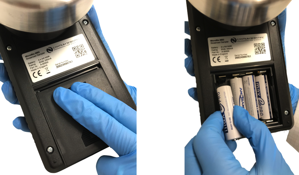
Carefully replace the lid with an upwards sliding motion ensuring the “OPEN” marking on the lid is towards the serial number label.
NOTE:
Please read the instructions supplied with the charger before charging the NiMh cells. To avoid corrosion, we recommend cells are removed from the unit if it is to be left unused for extended periods and fully charged before use.
8.2. External Power (optional)
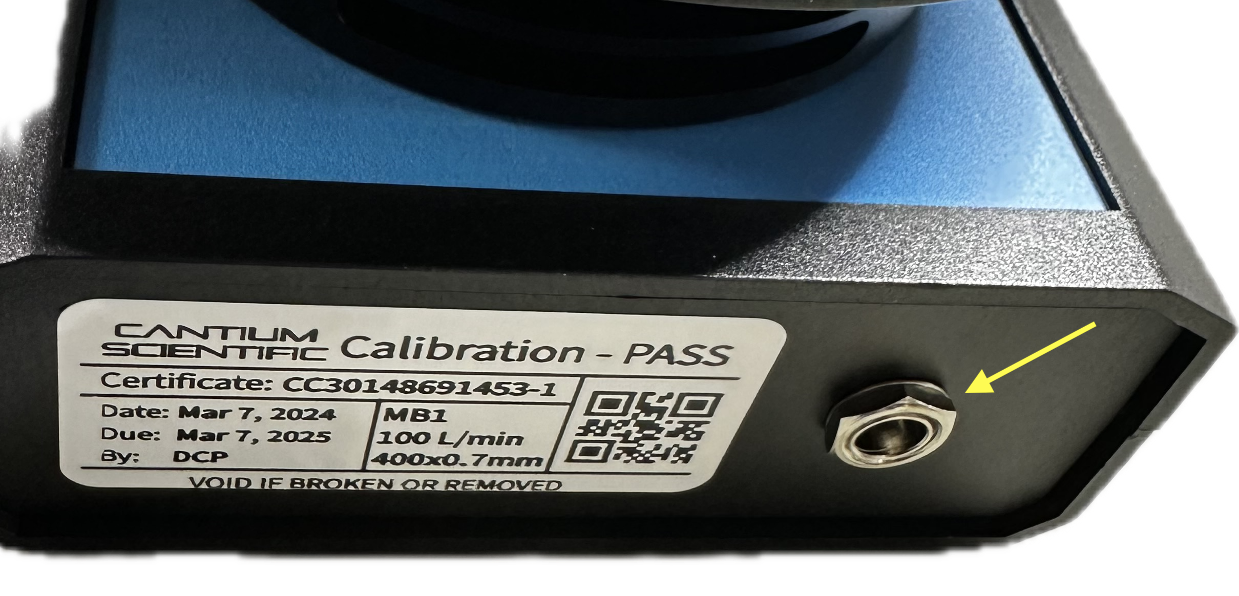
Available as an optional extra, the MicroBio MB1 can be powered from an external 5V to 9V DC source. When this option is fitted, a USB type A to 2.1 mm DC power jack cable is supplied that enables use of the battery charger power supply as the external power source. The cable also enables the MicroBio MB1 to be powered for any other USB type A power source rated at 2.4A.
The DC power inlet connector on the MicroBio MB1 is located as shown below:
9. Battery Management
The air blower in the MicroBio MB2 requires the use of cells that are capable of high current drain. Low cost alkaline or budget rechargeable cells are often not capable of delivering the required power while maintaining their terminal voltage and the sampler may stop operating without warning.
We recommend using the NiMH cells supplied with the sampler kits, or equivalent high quality cells with suitably low impedance. Alternatively, non-rechargeable alkaline cells may be used, but must be high quality, such as Duracell, Energizer or Varta industrial range. If using alkaline cells, the battery type needs to be manually set. Please see the ‘Settings’ section of this manual for instructions.
As cells age through time and use, their internal electrical resistance (impedance) increases. This will reduce the amount of time the sampler can be used on a single charge. Old cells may, at random, when under load drop their terminal voltage too low and the sampler will switch off. If this happens, the cells must be replaced. If this occurs during sampling, the sample must be discarded and a new one taken.
All cells at the end of their life should be recycled or disposed of responsibly in accordance with local regulations.
10. IQ / OQ / PQ
Documentation is available from Cantium Scientific Limited or your local distributor to support in-house Installation, Operational and Performance Qualification.
11. Sampling
The selection of the sample volume is important for reliable sampling. If the contact plate or petri dish is overloaded with colonies it is difficult to make an accurate count. With experience, the user will anticipate the probable bioaerosol concentration in an area, but it may be necessary to make a preliminary survey at a number of sampling volumes to identify the optimum setting. Each sample should be repeated several times and a statistical mean value and confidence value determined.
12. Selection of Media
The agar media used in the contact plate or petri dish should be chosen to suit the micro-organisms being monitored. For a wide range of micro-organisms, consider using tryptone soy agar (TSA), casein soy peptone agar (CPSA) or nutrient agar (NA). There are other selective agars for more specific micro-organisms. For fungi (yeasts and moulds), consider using malt extract agar (MEA) or rose bengal agar (RBA). Appendix C details various culture media types.
13. Inserting a Contact Plate or Petri Dish
ALWAYS STERILISE THE SAMPLING HEAD PRIOR TO EACH USE.
USE OF HYGIENE GLOVES IS RECOMMENDED
Carefully remove the sampling head cover from the MicroBio MB2, unless it is being carried separately in a sterile container. Only hold the edge of the head - do not touch the perforated or inside surfaces.
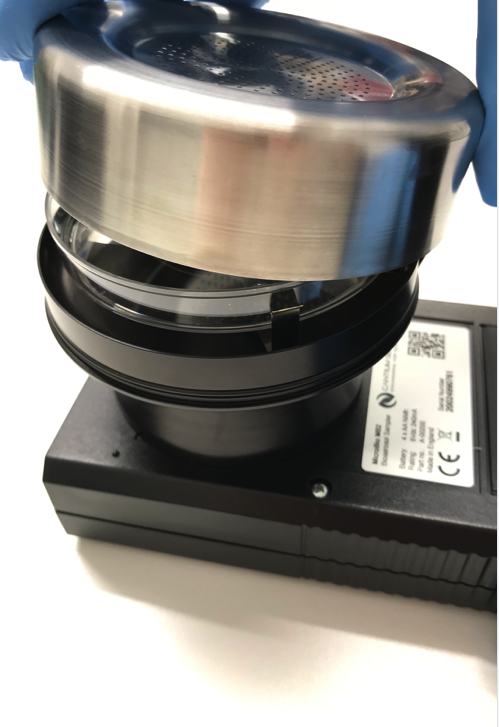
With the sampling head removed, insert a petri dish/contact plate inside the springs, so that its base sits firmly on the support plate, then re-fit the sampling head.
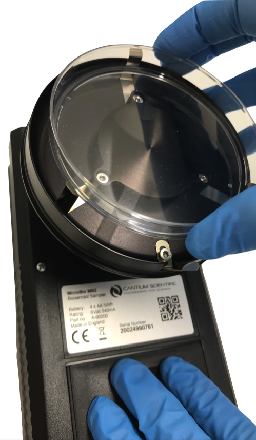
The standard MicroBio MB2 can use 220 or 400 hole sampling heads. The 220 hole sampling head can be used with both 55mm/65mm contact plates or 90mm petri dishes, but only the centre 55mm of the petri dish will collect samples. Using the 400 x 0.7mm hole sampling head will give nearly full coverage of a 90mm petri dish, improving reliability of counts. The MicroBio MB2-HiFlow model can only use 90mm Petri dishes and the 400 x 1mm hole sampling head.
14. Dust Cover (optional)
This accessory protects the media support plate and blower inlet of MicroBio MB1 from contamination during transport and setup. It is manufactured from autoclave-safe 316 grade stainless steel.

15. Keypad Controls
16. Switching On and Off
To switch the unit on press the ON/OFF  button.
The MicroBio MB2 will initially indicate the battery condition:

If the battery is too low, the MicroBio MB2 will issue a warning to change the battery and then automatically switch off. This is to protect the battery pack and not allow samples to be taken that may not complete.

To switch off the MicroBio MB2, press the ON/OFF  button.
The MicroBio MB2 will automatically switch off after a period of inactivity. Automatic and manual switch off is prevented during sampling, delayed start and sequential sampling. When switching off, a warning will sound and the display will show “switching off” while the MicroBio MB2 saves usage data to memory.
17. Take a Sample

When switched on the unit immediately enters Take Sample mode. This mode can also be selected by pressing the MENU button to show the following screen, then pressing the SELECT button.

Select the volume to be sampled by choosing a preset or manually adjust volume. Press ⊖ button to select preset option or ⊕ to select manual adjustment. Press the SELECT button to confirm.


If Preset Volume is selected, use ⊕ or ⊖ to select one of nine preset volumes, then press the SELECT button to begin sampling.

If Adjust Volume is selected, use ⊕ or ⊖ to set the required volume from 10 to 10000 litres. Press the SELECT button to begin sampling.

During sampling the display will show the sampled volume taken and the time remaining before sampling is complete.

At the end of sampling, the screen will display the total volume sampled and sound a warning tone and flash the top-mounted LED. To clear the warning, press any button. If left, the unit will automatically switch off after 20 seconds.

To cancel sampling at any time press and hold the MENU button. The unit will sound a short warning tone and display the volume sampled up to that point.
18. Delayed Sample
The Delayed Sample feature allows the user to set the MicroBio MB2 to start sampling after a given time between 1 minute and 3 hours. Select this option by pressing MENU, then pressing the SELECT button.

The delay time is adjusted using ⊕ or ⊖. When set, press the SELECT button.

The sample volume is set as described in Take Sample. Pressing the SELECT button will start the delay timer and the screen will show the countdown. During countdown the screen backlight will switch off to conserve battery power.

When the countdown reaches zero, sampling will start. The screen will display the volume sampled and remaining time. When finished, press any button or leave the MicroBio MB2 to automatically switch off.
19. Sequential Sampling

The Sequential Sampling feature allows sampling onto a single plate over an extended period of time. This is achieved by taking a sequence of smaller volumes over a programmable time, up to 24 hours. This is useful in clean room environments where contamination levels are normally low, resulting in low counts. Monitoring for short periods could risk missing potential hazards that may occur during the day. The MicroBio MB2 can be set up and left to work autonomously, sequential sampling up to 10000 litres over a 24 hour period.
19.1. Sequential Sampling – How it works
A cubic meter of air would normally be sampled in 10 minutes using a standard MicroBio MB2. Sequential sampling allows the user to configure the total volume to be sampled, by using an adjustable volume or one of the user preset volumes, over 5 minutes to 24 hour period with optional delayed start if required.
To illustrate how sequential sampling works, consider a 1000 litre sample taken over an 8 hour period (tp), broken into five separate samples (n). These numbers are entered into the MicroBio MB2 following a simple set of questions. The MicroBio MB2 then calculates how much air needs sampling per sequence (ts being the time to take each sample) and the time between the samples (ti), calculated using the equation below:
| |
The sampling sequence illustrated below, shows how the sample is broken down into five smaller samples of 200 litres each. ts for a standard MicroBio MB2 will be 2 minutes for each 200 litres of air.

Using the equation above, the interval between each of these 200 litre samples is calculated as 7050 seconds or 1 hour, 57 minutes and 30 seconds. At the end of the sampling sequence the MicroBio MB2 displays a finished message and will automatically power off. When the MicroBio MB2 is next switched on, it will display a finished message with the total volume of air sampled.
19.2. Taking a Sequential Sample

Navigate to this option using the MENU button and press the SELECT button.
Select the volume to be sampled by choosing a preset or manually adjust volume. Press ⊖ button to select preset option or ⊕ to select manual adjustment. Press the SELECT button to confirm selection.


If Preset Volume is selected, use ⊕ or ⊖ to select the required preset volume, then press the SELECT button.

If Adjust Volume is selected, use ⊕ or ⊖ to set the required volume to be sampled, then press the SELECT button. The volume may be set in the range of 10 to 10000 litres.

Next define the time over which sampling is to take place.

Use ⊕ or ⊖ to set the required time, from 5 minutes to 24 hours, then press the SELECT button.
Enter the number of sequences (2 to 100) using ⊕ or ⊖, then press the SELECT button.

Finally, define the time delay before sampling starts. Adjust from 0 for no delay up to 3 hours using ⊕ or ⊖ then press the SELECT button.

The MicroBio MB2 will calculate the volume each sequence is to take and the interval time between each sample.
Sequential Sampling process will commence, displaying a countdown if a delay was set. The first sample will be taken, then wait for the calculated interval before taking the next sample. This will continue until the total volume has been sampled over the required time.
During sequential sampling, the display will show a count of sequences (top-left), the total volume taken (bottom-left), time to next sample (top-right) and time remaining until sequential sampling is complete (bottom-right).

At the end of sequential sampling, the screen will indicate sampling is complete and the total sampled volume. The MicroBio MB2 will automatically switch off.
At any time, either during set-up or sampling, the process can be terminated by holding down the MENU button. If sampling is interrupted, the unit will display a summary of what has been sampled.
20. User Presets
Factory default preset volumes are 100, 200, 400, 500, 750, 1000, 2000, 5000 and 10000 litres. However, the User Preset feature allows modification of the nine preset volumes. Press the MENU button to navigate to this option, then press the SELECT button.

The user is presented with Preset Volume [1] and the current set volume. This value can be adjusted using ⊕ or ⊖. Users can set the volume between 10 and 10000 litres.

When the desired volume is reached press the SELECT button to store and move on to the next preset. When all required presets have been set, press the MENU button to save and exit this option. Settings are stored in non-volatile memory and are retained when the battery is removed.
21. Unit Status
Unit Status displays information about the MicroBio MB2. Press the SELECT button to select this mode, then ⊕ or ⊖ to navigate through the information.
Pressing the MENU button will exit this mode.

21.1. Battery Level Display
Displays a percentage of battery capacity and voltage at rest. The capacity is only an approximation and cannot be used to determine the exact remaining sampling capacity.

21.2. Power Diagnostics
This information is only of use during service and repair of the sampler.

21.3. Total Volume Count
Displays the total litres of air the MicroBio MB2 has sampled since the last factory reset. This figure is useful for manufacturer’s maintenance and reliability statistics and may also be used as an indicator for the user’s regular calibration regime.

21.4. Total Samples Taken
Displays a count of how many samples have been taken by the MicroBio MB2 since the last factory reset. This figure is useful for the manufacturer’s maintenance and reliability statistics and may also be used as an indicator for the user’s regular calibration regime.

21.5. Unit Version
Displays the hardware and software revision information for the MicroBio MB2. It is used by the manufacturer for repair and maintenance purposes. The software in the MicroBio MB2 cannot be upgraded by the user.

21.6. Restore Factory Defaults
When Unit Status mode is selected, it is possible to perform a factory reset on the MicroBio MB2 by holding down ⊕ and ⊖ simultaneously. The sampler will restart and initialise all settings to factory defaults and reset the total counts to zero.
22. Settings
Unit settings include Language, Battery Type and Auto power-off time.

Press the SELECT button to select this mode, then ⊕ or ⊖ to navigate options. Pressing the MENU button will exit this mode. Pressing the MENU button at any time when in the settings options will also exit.
22.1. Settings - Language
When the language setting option is shown, press the SELECT button.

Use ⊕ or ⊖ to select required language, then press the SELECT button.

22.2. Settings - Battery Type
The MicroBio MB2 is capable of operating on non-rechargeable alkaline cells or rechargeable NiMH cells. However, these cells have different electrical characteristics and the MB2 needs to know what type is installed so as to properly report on battery level.
The default setting is for NiMH cells, as supplied with the MicroBio MB2.
When the option is shown on the screen, press the SELECT button to select.

Use ⊕ or ⊖ to select the battery type, then press the SELECT button to store the setting.


Selecting the wrong type will not cause any harm to the MicroBio MB2 or the cells, but will give incorrect reporting of capacity.
22.3. Settings - Automatic Power Off
By default, the MicroBio MB2 will power off after 60 seconds of inactivity. This can be adjusted if required from 10 seconds to 5 minutes, or disabled.

When the Auto-off option is shown on the screen, press the SELECT button.

Use ⊕ or ⊖ to change the auto-off time, then press the SELECT button to store.
To disable the automatic power-off feature keep the ⊖ button held until the display shows disabled.

23. Tripod Mounting
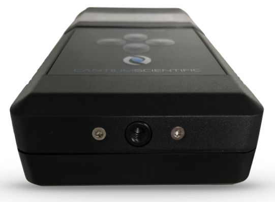
The MicroBio MB2 incorporates a standard ¼”-20 UNC tripod mount, as defined in ISO1222:2010. Tripods designed for most photographic equipment are compatible with the MicroBio MB2.
24. Temperature and Humidity
It is useful to measure these at the time of each sample. Temperature and humidity are important factors in the likely concentration and viability of airborne micro-organisms. For example, some bacteria survival rates are 35 to 65 times higher at 80%RH compared to 40%RH.
25. Determining Results
Once the sample has been taken, the contact plate or petri dish should be removed and sealed with its protective lid. A note should be made on the lid regarding time, location and volume sampled.
The plate should then be incubated for a period of time and temperature dependant on the requirements of the media. Once incubated, the colony growths are then counted, either manually or using an automatic colony counter. Due to the statistical nature of the sampling method and the chance more than one colony impinged at one point on the dish, a count correction needs to be performed.
The tables in Appendix A and Appendix B give the corresponding corrected value for the 220 hole and 400 hole sampling heads respectively.
Alternatively, the following equation can be used to determine a corrected count.
| |
Where nh is the number of holes on the sampling head, nf is the number of counted colonies and nc is the corrected count.
If the counted colonies, (nf) exceeds the number of sampling head holes (nh), then the equation will fail and the results cannot be trusted. If this is the case, then the sample dish can be considered as overloaded with micro-organisms and the user should consider lower sampling volumes.
The colony concentration is the corrected count per volume of air sampled. The results are normally expressed in colony forming units per cubic metre.
To convert the corrected count to CFU/m3 use the equation:
| |
Where nc is the corrected number of colonies counted and Vs is the sampled volume in litres.
An online count correction tool and spreadsheets to automate correction and collation of results are available for free download from:
26. Change Plate / Dish Type
The MicroBio MB2 with a 220 hole sampling head can accommodate both 55mm/65mm contact plates or 90mm petri dishes. The MicroBio MB2 is factory fitted with the petri dish springs (Cantium Scientific Limited part number A-00070), but these can be removed and replaced with the supplied contact plate springs (Cantium Scientific Limited part number A-00068).
The springs for both types have slots to allow a degree of adjustment to suit dish/plate manufacturer variations.
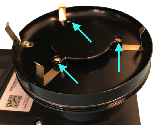
To change the spring type remove the three screws as highlighted using the 2mm hex-key supplied with the kit. Lift off the support plate and springs, then refit using the same screws, support plate and the required springs. Care must be taken not to over-tighten or cross-thread any of the screws.
Replacement screws are available from Cantium Scientific Limited part number A-00232 or contact your local distributor.
27. Head Seal Maintenance
A Nitrile-70 O-ring is used on the head assembly to provide an air tight seal. With age and cleaning, this may deteriorate and need to be replaced, but typically last at least 5 years.
A replacement is included with the MicroBio MB2 kit, but extras are available from Cantium Scientific Limited, part number A-00227.
28. Cleaning
The sampling head should be sterilised preferably by autoclave, but in the field disinfect with suitable sterilising wipes, such as IPA wipes. Wipes may also be used for general cleaning of the sampler body.
Caution: Do not use caustic based cleaning methods.
In areas of low bioaerosol levels, observe a disinfection regime between each sample. Always sample from areas of lower contamination towards those of higher contamination. Wash exposed skin and clothing before sampling and avoid drinking, eating and smoking in the test area or around the equipment. All equipment should be handled aseptically.
The MicroBio MB2 is suitable for use with Hydrogen Peroxide Vapour (H2O2 vapour) bio-decontamination. As the MicroBio MB2 has a fan within the sampling head, it is recommended for optimum decontamination the MicroBio MB2 is set to sample at maximum volume, allowing H2O2 vapour to be drawn through the head, fan and exhaust. Tests have been carried out by Bioquell (UK) Ltd on a range of sensitive electronic equipment to determine effects of such processes. The conditions of these tests were:
Gas Concentration |
1000 ppm |
Conditioning time |
20 minutes |
Gassing time |
30 minutes |
Aeration time |
150 minutes |
Vapour sterilisation above the test conditions levels and times will invalidate the warranty.
Throughout the tests, Bioquell demonstrated that bio-decontamination with H2O2 vapour does not appear to be detrimental, affect operational aspects or aesthetics of sensitive electronic equipment. For further information, please refer to document BDS-3-MATCOMP-V3.2, available from Bioquell (UK) Ltd upon request.
29. Validation
Some industries require sampling equipment to be validated before each use. For the 100 L/min MicroBio MB2 and MB2-RSH this can be achieved using the MicroBio Validation Kit, part number A-00058 available from Cantium Scientific Limited or your local distributor. For the MB2-HiFlow, validation can be achieved using the Qualisair™ qCR kit, Cantium Scientific Limited part number A-00422.
30. Calibration
It is recommended all models of MicroBio MB2 are regularly calibrated in accordance with specific industry best practice. Typically, this will be on the anniversary of the instrument entering service.
The only calibration adjustment on the instrument is the flow rate. Calibration is normally performed at an air pressure of 1013 mbar at 20ºC.
For calibration services please contact Cantium Scientific Limited or your local distributor. For in-house calibration, we recommend the use of the Qualisair™ qCR kit, available from Cantium Scientific Limited or your local distributor.
31. Troubleshooting and Technical Support
The MicroBio MB2 will give many years of trouble-free service with minimal routine maintenance. However, below are some common questions and answers relating to the use of the MicroBio MB2 Bioaerosol Sampler.
Q. The unit will not switch on.
A. Check the cells are inserted correctly and fully charged. If this does not resolve the situation, replace the cells and try again. If this fails to resolve the issue, please contact your local distributor or Cantium Scientific Limited for technical support.
Q. The sampler switches off when starting or during sampling.
A. This is due to exhausted, low quality or dead cell(s) in the battery. Replace all cells or recharge. Low quality cells may present a correct terminal voltage, but as soon as a load is applied, this will drop drastically below a point where the sampler will not function. Please refer to the battery management section of this manual for further information.
Q. The sampling head fits loosely.
A. There is a retaining spring inside the sampling head area that keeps the head tight. This may, with time and use have moved. Loosen the screw, slide the spring to the edge of the sampling head plate and re- tighten using the hex-key supplied with the kit. Do not over-tighten the screw. There is a nitrile O-ring on the sampling head assembly that may have worn. A replacement O-ring is supplied with the kit (part no. A-00227).
Q. The contact plate or petri dish fits loosely.
A. With time the springs that hold the plates/dishes may have stretched out of shape. Undo the screws holding the springs and support plate using the hex-key supplied, move the springs and re-tighten until a secure hold of the plate/dish is obtained. There is variation in the outside diameter of plates/dishes between manufacturers. The MicroBio MB2 holding springs can be adjusted to accommodate this variation.
31.1. Technical Support
Technical support is available at our technical support portal.
This site provides a search facility for issues, with many support articles and a facility to post questions. Alternatively, contact your distributor.
32. Appendix A - 220 Hole Count Correction Table
Note: For counts greater than those shown in the table below, please refer to ‘Determining Results’ section or visit https://www.cantiumscientific.com/support/count-correction/
Count |
Corrected |
Count |
Corrected |
Count |
Corrected |
Count |
Corrected |
1 |
1 |
41 |
46 |
81 |
101 |
121 |
175 |
2 |
2 |
42 |
47 |
82 |
102 |
122 |
177 |
3 |
3 |
43 |
48 |
83 |
104 |
123 |
179 |
4 |
4 |
44 |
49 |
84 |
106 |
124 |
182 |
5 |
5 |
45 |
50 |
85 |
107 |
125 |
184 |
6 |
6 |
46 |
52 |
86 |
109 |
126 |
186 |
7 |
7 |
47 |
53 |
87 |
110 |
127 |
188 |
8 |
8 |
48 |
54 |
88 |
112 |
128 |
191 |
9 |
9 |
49 |
56 |
89 |
114 |
129 |
193 |
10 |
10 |
50 |
57 |
90 |
115 |
130 |
196 |
11 |
11 |
51 |
58 |
91 |
117 |
131 |
198 |
12 |
12 |
52 |
59 |
92 |
119 |
132 |
201 |
13 |
14 |
53 |
61 |
93 |
120 |
133 |
203 |
14 |
15 |
54 |
62 |
94 |
122 |
134 |
206 |
15 |
16 |
55 |
63 |
95 |
124 |
135 |
208 |
16 |
17 |
56 |
65 |
96 |
126 |
136 |
211 |
17 |
18 |
57 |
66 |
97 |
127 |
137 |
213 |
18 |
19 |
58 |
67 |
98 |
129 |
138 |
216 |
19 |
20 |
59 |
69 |
99 |
131 |
139 |
219 |
20 |
21 |
60 |
70 |
100 |
133 |
140 |
222 |
21 |
22 |
61 |
71 |
101 |
135 |
141 |
224 |
22 |
23 |
62 |
73 |
102 |
136 |
142 |
227 |
23 |
24 |
63 |
74 |
103 |
138 |
143 |
230 |
24 |
26 |
64 |
76 |
104 |
140 |
144 |
233 |
25 |
27 |
65 |
77 |
105 |
142 |
145 |
236 |
26 |
28 |
66 |
78 |
106 |
144 |
146 |
239 |
27 |
29 |
67 |
80 |
107 |
146 |
147 |
242 |
28 |
30 |
68 |
81 |
108 |
148 |
148 |
245 |
29 |
31 |
69 |
83 |
109 |
150 |
149 |
248 |
30 |
32 |
70 |
84 |
110 |
152 |
150 |
251 |
31 |
34 |
71 |
86 |
111 |
154 |
151 |
254 |
32 |
35 |
72 |
87 |
112 |
156 |
152 |
257 |
33 |
36 |
73 |
89 |
113 |
158 |
153 |
261 |
34 |
37 |
74 |
90 |
114 |
160 |
154 |
264 |
35 |
38 |
75 |
92 |
115 |
162 |
155 |
267 |
36 |
39 |
76 |
93 |
116 |
164 |
156 |
271 |
37 |
41 |
77 |
95 |
117 |
166 |
157 |
274 |
38 |
42 |
78 |
96 |
118 |
168 |
158 |
278 |
39 |
43 |
79 |
98 |
119 |
170 |
159 |
282 |
40 |
44 |
80 |
99 |
120 |
173 |
160 |
285 |
33. Appendix B - 400 Hole Count Correction Table
Note: For counts greater than those shown in the table below, please refer to ‘Determining Results’ section or visit https://www.cantiumscientific.com/support/count-correction/
Count |
Corrected |
Count |
Corrected |
Count |
Corrected |
Count |
Corrected |
1 |
1 |
41 |
44 |
81 |
91 |
121 |
144 |
2 |
2 |
42 |
45 |
82 |
92 |
122 |
145 |
3 |
3 |
43 |
46 |
83 |
93 |
123 |
147 |
4 |
4 |
44 |
47 |
84 |
95 |
124 |
148 |
5 |
5 |
45 |
48 |
85 |
96 |
125 |
150 |
6 |
6 |
46 |
49 |
86 |
97 |
126 |
151 |
7 |
7 |
47 |
50 |
87 |
98 |
127 |
153 |
8 |
8 |
48 |
51 |
88 |
100 |
128 |
154 |
9 |
9 |
49 |
53 |
89 |
101 |
129 |
156 |
10 |
10 |
50 |
54 |
90 |
102 |
130 |
157 |
11 |
11 |
51 |
55 |
91 |
103 |
131 |
159 |
12 |
12 |
52 |
56 |
92 |
105 |
132 |
160 |
13 |
13 |
53 |
57 |
93 |
106 |
133 |
161 |
14 |
14 |
54 |
58 |
94 |
107 |
134 |
163 |
15 |
15 |
55 |
59 |
95 |
109 |
135 |
164 |
16 |
16 |
56 |
61 |
96 |
110 |
136 |
166 |
17 |
18 |
57 |
62 |
97 |
111 |
137 |
167 |
18 |
19 |
58 |
63 |
98 |
113 |
138 |
169 |
19 |
20 |
59 |
64 |
99 |
114 |
139 |
170 |
20 |
21 |
60 |
65 |
100 |
115 |
140 |
172 |
21 |
22 |
61 |
66 |
101 |
117 |
141 |
174 |
22 |
23 |
62 |
68 |
102 |
118 |
142 |
175 |
23 |
24 |
63 |
69 |
103 |
119 |
143 |
177 |
24 |
25 |
64 |
70 |
104 |
121 |
144 |
178 |
25 |
26 |
65 |
71 |
105 |
122 |
145 |
180 |
26 |
27 |
66 |
72 |
106 |
123 |
146 |
181 |
27 |
28 |
67 |
74 |
107 |
125 |
147 |
183 |
28 |
29 |
68 |
75 |
108 |
126 |
148 |
184 |
29 |
30 |
69 |
76 |
109 |
127 |
149 |
186 |
30 |
31 |
70 |
77 |
110 |
129 |
150 |
188 |
31 |
33 |
71 |
78 |
111 |
130 |
151 |
189 |
32 |
34 |
72 |
80 |
112 |
131 |
152 |
191 |
33 |
35 |
73 |
81 |
113 |
133 |
153 |
192 |
34 |
36 |
74 |
82 |
114 |
134 |
154 |
194 |
35 |
37 |
75 |
83 |
115 |
136 |
155 |
196 |
36 |
38 |
76 |
85 |
116 |
137 |
156 |
197 |
37 |
39 |
77 |
86 |
117 |
138 |
157 |
199 |
38 |
40 |
78 |
87 |
118 |
140 |
158 |
200 |
39 |
41 |
79 |
88 |
119 |
141 |
159 |
202 |
40 |
42 |
80 |
90 |
120 |
143 |
160 |
204 |
34. Appendix C - Culture Media Types
Some examples of culture media are given in the table below. However, always check with your supplier for the optimum medium to use for your specific application.
Micro-organism |
Agar Culture Medium |
Incubation Temperature |
Bacteria: |
||
Human Flora |
Blood Agar |
35 - 37°C |
Possible Pathogens |
Heart Infusion Agar |
35 - 37°C |
Environmental saprophytic |
SCDA or R2A |
25 - 30°C |
Thermophylic |
EMB or Endo Agar |
35 - 37°C |
Fungi: |
||
Environmental saprophytes |
Malt Extract Agar(MEA) |
Room Temp |
|
Sabouraud Dextrose |
Room Temp |
|
Rose Bengal Agar (RBA) (with streptomycin), Inhibitory Mould Agar |
20 - 25°C |
Xerophylic |
Malt Extract Agar with added NaCl, sucrose or dichloran-glycerol |
20 - 25°C |
35. Appendix D - Replacement Parts
Description |
Part Number |
55mm contact plate holding springs |
A-00068 |
90mm Petri dish holding springs |
A-00070 |
Head retaining spring |
A-00071 |
2mm Hex-key |
A-00206 |
MB2 nitrile head O-ring |
A-00227 |
Battery charger |
A-00688 |
NiMH rechargeable cell pack |
A-00441 |
Mini tripod |
A-00061 |
220 x 1.0mm stainless steel sampling head |
A-00021 |
400 x 0.7mm aluminium sampling head |
A-00020 |
400 x 0.7mm stainless steel sampling head |
A-00670 |
400 x 1.0mm stainless steel sampling head (HiFlow only) |
A-00183 |
MicroBio Dust Cover |
A-00771 |
Hard carry case |
A-00060 |
36. Appendix E - MB2-RSH Installation
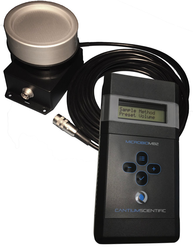
The first task is to run the connecting cable from where the sampling head is to be positioned to where the control unit is to be located. A connector is pre-fitted to the cable end to be connected to the remote sampling head. Multiple connector options are possible, but the following describes the standard screw locking connector.
36.1. Fitting the Connector for Unterminated Cables
The following tools are required to fit the connector:
1 x Soldering iron and solder (lead free)
1 x 2.5mm slot screwdriver
The connector is assembled in the order as shown in the photographs below.
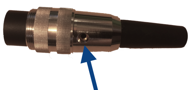
Dismantle the connector by first removing the screw on the side of the connector.
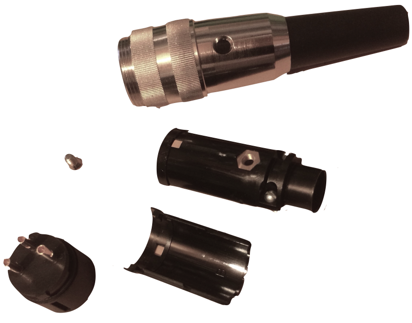
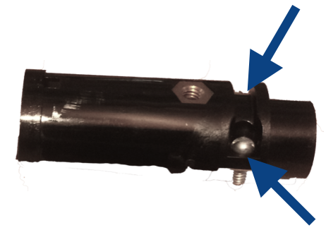
Slide the metal connector housing onto the cable end, followed by the strain relief. The strain relief will need pushing on firmly.Remove cable clamp.

Remove cable clamp.
Solder cable onto connector pins. The connector body has pin numbers embossed onto the surface adjacent to the pins.
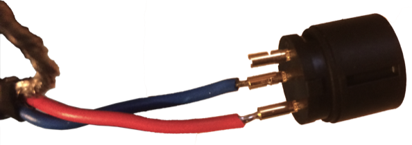
Pin 1: Red
Pin 2: Blue
Fit frame onto cable end and refit cable clamp. The clamp must clamp on the outer sheath/heat-shrink on the end of the cable. Then solder the screen agains the soldier tab of the frame.
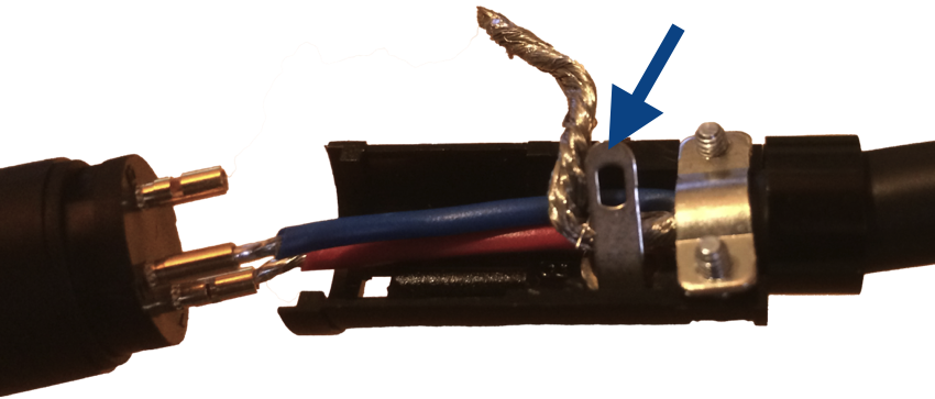
Fit the pin housing back onto the frame, noting the raised pegs on the rim of the pin housing that sit into the holes on the frame. Then replace the frame cover.
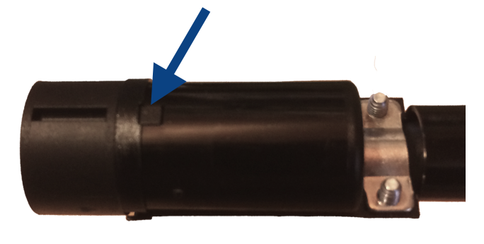
Slide the assembly, strain relief and metal shell together.

Align shell so that the brass thread of the frame body can be seen, then replace the housing screw and tighten.
36.2. Connecting
The connectors are polarised so that they can only be connected in the correct manner. The remote head unit requires the female connector and the male connector end of the cable connects to the control unit.
36.3. Operation
Once installed, the MB2-RSH operates in exactly the same way as a conventional MB2 bioaerosol sampler.
Calibration
Factory or Service Agent only
The MB2-RSH can be calibrated in the same manner as any other MicroBio bioaerosol sampler.
Disconnect the head and control unit from the cable and return to the manufacturer or approved agent for calibration. Head units must be thoroughly cleaned, sterilised and free from any potential contaminant before return to a calibration agent.
Documented evidence of cleaning must be provided.
Please inform the calibration provider of the length of the connecting cable used for the controller and head combination. It may be possible to calibrate in situ. The use of the Qualisair™ qCR kit is required for this.
36.4. Cleaning
Cleaning of the control unit can be carried out as on the standard MB2 models. However, cleaning of the sampling head unit must follow the site procedures for cleaning within the isolator cabinet.