WI422 - Air Sampler Calibration Using Qualisair qCR Calibration Kit
The Qualisair™ qCR Calibration Kit is the standard device used to calibrate the following models of bioaerosol samplers only:
MicroBio MB1 (100 litres per minute)
MicroBio MB1 (180 litres per minute)
MicroBio MB2 (100 litres per minute)
MicroBio MB2-HiFlow (180 litres per minute)
MicroBio MB2-RSH (100 litres per minute)
MicroBio MB2-RSH-HiFlow (180 litres per minute)
Qualisair samplers (100 and 200 litres per minute)
Reference should be made to the calibration methods required for the range of samplers:
MB1 (February 2023 models onwards) Calibration procedure
MB2 (2022 models onwards) Calibration procedure
Using the calibration certificate spreadsheet
1. Important Notes
The laboratory environment is recommended to be 20ºC ±2ºC at 1013.25mBar ± 10mBar and >50%RH <80%RH with minimal air movement around the sampler under test.
For faults discovered during inspection and calibration:
For Cantium staff: Product Calibration, Service, Fault Finding and Repair
For Service Agents & Distributors: Product Fault Finding & Repair (password protected)
Cantium Scientific Staff Only:
Any faults found during inspection and calibration of new products require submission of a non-conformity report:
Required |
Precautions |
Qualification Level |
|---|---|---|
Qualisair qCR Kit |
NOTE: It is important not to obstruct the exhaust vents of the sampler or the inlet of the calibration rig during the test. NOTE: The upper tube on the calibration rig has air flow guide tubes inserted around the inner wall. DO NOT TOUCH THE GUIDE TUBES. NOTE: Ensure the sampler is calibrated using fresh or charged cells. Observe all hygiene procedure where the calibration is to be performed. It is recommended that suitable gloves and other PPE suitable for use in the calibration environment are worn during the calibration procedure. |
Technician |
2. Procedure
Step |
Action |
|
|---|---|---|
1 |
Check the calibration date of the Qualisair™ qCR Calibration Kit to ensure it is current.
Note: This device is for use only by qualified personnel with suitable training and experience. Please contact Cantium Scientific Limited for further details. |
|
2 |
Prior to starting calibration work, ensure the kit contents are complete as listed below: 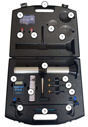
|
|
3 |
Examine qCR kit calibration certificate to ensure date of use is within the certificate date range. If not, then stop work and send the qCR kit for calibration. |
Note: The Barometer is for indication only and does not form part of the calibration computations. Since 2022, the barometer is not supplied and does not form part of the process. |
4 |
Ensure sufficient spares are within the Spares Pack. 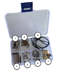 |
|
5 |
Calibration and validation should be carried out in a controlled environment and on a level surface. Air movement around the calibration zone should be minimised and ideally carried out in normal atmospheric pressure of 1013 mbar at 20°C. |
|
6 |
Ensure the sampler has a fresh/charged battery pack. |
|
7 |
If the sampling head mount of the sampler has an O-ring seal for air tightness, then ensure this is in good condition. Particularly for post 2017 MicroBio MB2 models. Replacement seals are supplied with MB2 models and contained in the spares pack of the Qualisair™ qCR kit along with an O-ring pick tool. |
|
8 |
Check all the holes in the sampling head are clear. If not, then supplied in the Qualisair™ qCR kit are 1.0mm and 0.7mm drills to assist in removing any blockages. |
|
9 |
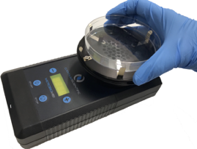
Insert either 90mm petri dish or 55mm contact plate, depending on the configuration of the sampler. |
 |
10 |
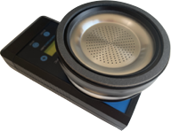
If calibrating a MicroBio model of sampler, then the MicroBio adapter ring must be fitted onto the MicroBio sampling head before fitting the calibration rig. Qualisair™ models will not require the adapter. |
 |
11 |
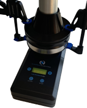
Place the calibration rig onto the top of the sampling head, or on top of the adapter ring, then clamp using the supplied mini quick-clamps. Only light pressure is required - do not over tighten. Ensure the faces of the clamps fit in the recesses on the calibration rig to ensure stability. |
 |
12 |
Switch on the anemometer on the calibration rig by pressing the power button. The display on the anemometer may be angled to make viewing easier.
Note: The temperature reading is indicative only and does not form part of the calibration computations |
 |
13 |
Open the Sampler Calibration Certificate Template spreadsheet and save with a file name that refers to the serial number of the air sampler being calibrated. Before commencing calibration measurements, complete all necessary fields in the spreadsheet. Check the calibration factors M and C match those stated on the Qualisair™ qCR kit calibration certificate and all details under ‘qCR Kit Calibration Parameters’ are correct. Full details on using the certificate template can be found in Using the calibration certificate spreadsheet. |
|
14 |
Now perform general visual inspection and required remedial action taken for the sampler and record finding on the certificate spreadsheet. |
|
15 |
Start the sampler to sample at least 400 litres for a 100 litre per minute sampler and 1000 litres for a 180 or 200 litres per minute sampler. Please refer to the sampler operating manual for instructions on how to do this. |
|
16 |
Wait 30 seconds for the anemometer to stabilise. |
|
17 |
Every 10 seconds take a measurement from the anemometer until 12 readings have been taken. Record these in the Inspection column of the Measurements table on the certificate spreadsheet. Then allow the sampler to complete the sample. It is normal for readings taken to vary from the Anemometer Target value indicated on the Qualisair™ qCR calibration certificate. Read Using the calibration certificate spreadsheet for full details of using the spreadsheet. |
|
18 |
The spreadsheet computes the flow rate in Litres Per Minute from the twelve readings and performs statistical computation on the measurements to produce a confidence range of the measured flow rate. Based on the flow rate determined, the spreadsheet also computes a theoretical value for the d50 particle cut-off size and the inlet hole jet velocity for the sampler. |
|
19 |
If the flow rate is within allowable range, the spreadsheet will indicate ‘PASS’, otherwise it will indicate if the flow needs increasing or decreasing. The flow should be adjusted so that the required target velocity as indicated by the spreadsheet is achieved, then repeat the procedure from step 15 above. The method of adjustment depends on the model of sampler. |
|
20 |
The spreadsheet will again indicate a PASS or FAIL condition. If FAIL, then the air sampler should be removed from service and sent for further testing or repair by an approved service agent. |
|
21 |
If PASS is achieved, then a calibration label should be applied to the sampler. As a minimum this must include calibration date, next due date and the technician's initials. |
|