Estimating Required Fluid Volume
Objectives
- Maintain well control---ensure a full column of clear brine fluid of an adequate density
- Respond to pressure changes
- Plan for fluid contingency needs
Factors Affecting
- Well design and surface equipment
- Formation permeability
- Distance to the supply point
Discussion
Carefully estimating the required fluid volume will allow you to maintain an adequate volume of completion fluid to ensure smooth, uninterrupted completion operations.
Determination of the appropriate quantity of completion fluid should be based primarily on the capacity of the casing and tubing used during completion operations. The quantity of fluid circulating at any time is the total of the well volume, less the tubing displacement, plus all surface equipment, piping, pumps, tanks, and filtration equipment. Contingency planning for additional fluid needs will include potential fluid loss and density control. Finally, the distance to the supply point may suggest additional volume to ensure a timely response. As a general rule, the initial fluid order should be at least two to three times the circulating volume of the well.
Calculating Volume Requirements
A volume calculation worksheet should include the following:
- Circulating volume
- Holding tanks
- Filtration equipment
- Surface piping
- Contingency needs and pill demands
Circulating Volume
Determining the volume of the CBF required to fill the hole and maintain the required hydrostatic pressure is a matter of adding up the casing, liner, and openhole volumes and then subtracting the volume displaced by drill pipe or tubing.
Cased Hole with Tubing. Tables of standard API drill pipe, casing, liners, and tubing are provided in Chapter 6, "Tables, Formulas, and Planning Support." Formulas for pipe volume, annular volume, and velocity are also included in Chapter 6.
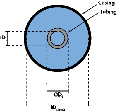
Figure 5 is a schematic of the two components of the downhole volume--- tubing volume and annular volume. Determining the fluid volume required can be made easy by using the internal capacities for the tubing or working string given in Table 19, “API Tubing — Weight, Dimensions, and Capacities,” and annular capacities in Table 20, “Annular Capacity.”
FIGURE 5. Combined Casing and Tubing

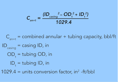
Values for combined tubing plus annular capacity in barrels per foot can be calculated using Equation 6. This equation also lends itself to spreadsheet applications for determining capacity.
EQUATION 6.

Holding Tanks
The tank capacity necessary for a CBF job is often substantially greater than that required for circulating a drilling fluid. Since brines are continuously filtered, two holding tanks are required, one for returning fluid that may be carrying solids and another of equal volume for filtered fluid. Holding tank volume may also be limited by rig space.
At least one complete hole volume should be available in surface holding tanks to allow filtration operations to keep pace with circulating requirements. |
Filtration Equipment
An allowance should be made for filtration equipment. A larger, high capacity plate and frame filter press with precoat tanks can hold up to 30 barrels of fluid. Table 5 gives some volumes of typical filtration equipment. A typical system will include filter, precoat and body feed tank, guard unit, pumps, and hoses.
TABLE 5. Typical Filtration Equipment Volumes
| Equipment | Volume (bbl) |
Precoat and Guard1* |
Total |
| SafeDEflo 600 and C600 | 5.3 | 24 | 29.3 |
| SafeDEflo 1100 | 7.1 | 24 | 31.1 |
| SafeDEflo 1300 | 8.4 | 24 | 32.4 |
| SafeDEflo 1500 | 9.6 | 24 | 33.6 |
^1{^}Precoat and Body Feed Tanks = 20 bbl and Guard Unit = 4 bbl
Surface Piping
Any unusual requirements for positioning equipment can result in additional volumes in hoses, pumps, and piping. An allowance of 10 barrels is a reasonable recommendation.
Contingency Planning and Pill Demands
Fluid Loss Pills. On occasion, it may become necessary to pump a viscous pill into the producing zone to slow fluid loss. The volume of the pill will be equal to at least the combined annular and tubing volume through the perforated zone plus some additional footage for safety. As a rule of thumb, about 1.5 times the volume of the perforated zone can be used.
Spike Material. Spike material, or spike fluid, is high density fluid that is transported to and stored on location in case it is necessary to raise fluid density in order to control pressure or respond to a kick. The volume usually ranges between 75 and 150 bbl of a selected high density blending stock. The volume of spike material that is held in reserve should be based on a number of factors, including:
- uncertainty regarding bottomhole pressure,
- treating dilutions of working fluid,
- available storage space on the location or rig,
- density difference between the working fluid and the spike fluid,
- environmental discharge/spill limitations, and
- cost considerations.
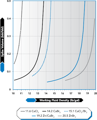
A detail that is often overlooked when determining the density and volume of spike material is the relative amount of spike fluid needed to raise the density of the working fluid by a particular increment. Often, it is more economical to use a much heavier spike fluid, even if its unit cost is higher. The reason for this is that it may take substantially less of the heavier spike material to obtain the same density increase. An illustration of this relationship is shown in Figure 6.
For example, it will take twice as much 19.2 lb/gal zinc/calcium bromide (ZnBr2/CaBr2) to raise the density of a 17.8 lb/gal working fluid by 0.2 lb/gal than it would if a 20.5 lb/gal ZnBr2 spike fluid was used. Half the volume of 20.5 lb/gal fluid could be transported and stored as spike fluid. In addition to the smaller storage needs of the higher density spike fluid, there is the added benefit that, when it is used to achieve a given density adjustment, it will create a smaller volume increase in the working fluid.
FIGURE 6. Selecting and Using Spike Fluids

Figure 6 shows the amount of spike fluid, in fractions of a barrel, it takes to raise the density of one barrel of any working fluid by an adjustment of 0.2 lb/gal. To use this guide, choose a density of working fluid along the bottom and lay a straight edge vertically through the chart to find the relative volume of fluid needed to make a 0.2 lb/gal adjustment.
Permeability and Pressure Conditions in a Producing Zone
Formation characteristics will play a large role in determining the amount of fluid that is held in reserve. Large quantities of fluid may be lost to highly permeable formations or formations that contain fracture permeability. Experience in a particular producing horizon may dictate carrying extra fluid inventory to allow for seepage into the formation.
Distance to the Supply Point
The distance to the nearest supply point, uncertainty about bottomhole conditions, and seasonal factors such as temperature changes should be considered in determining the volume delivered at the beginning of the job. Deepwater offshore platforms will probably have longer supply lead times than shallow water or onshore projects. In cases where substantial delays could impact operations, additional volume should be purchased to ensure that volume losses can be made up on a safe and timely basis in order to avoid delays.
Volume Calculation Worksheet
According to the general rule, the initial fluid order should be two to three times the circulating volume of the well. Another method for determining the initial fluid quantity is to use a tool similar to the volume calculation worksheet below.
Volume Calculation Worksheet |
|
| Equipment | Volume |
| Circulating Volume | |
| Holding Tanks | |
| Filtration Equipment | |
| Surface Piping | |
| Contingency Needs | |
| Total | |